It's been a while. Here's an update:
I found it hard to find time to do woodworking, and space became more and more limited over the years. I did a few projects here and there, including a few luthier jigs below. I also made a liquor cabinet for a coworker (also below).
About a year ago now, I began looking for a new job. I moved out to a more rural area a few months later. I finally found a new job about a month ago and now I have almost 3 extra hours a day during the week to do woodworking (shorter commute, fewer hours). I am tackling a rather large remodeling project with an end product being a 900 sqft shop and an attached loft. I started a project described below in the new shop, so you'll see the difference between the two locations. I do plan to document the remodeling project in a few weeks.
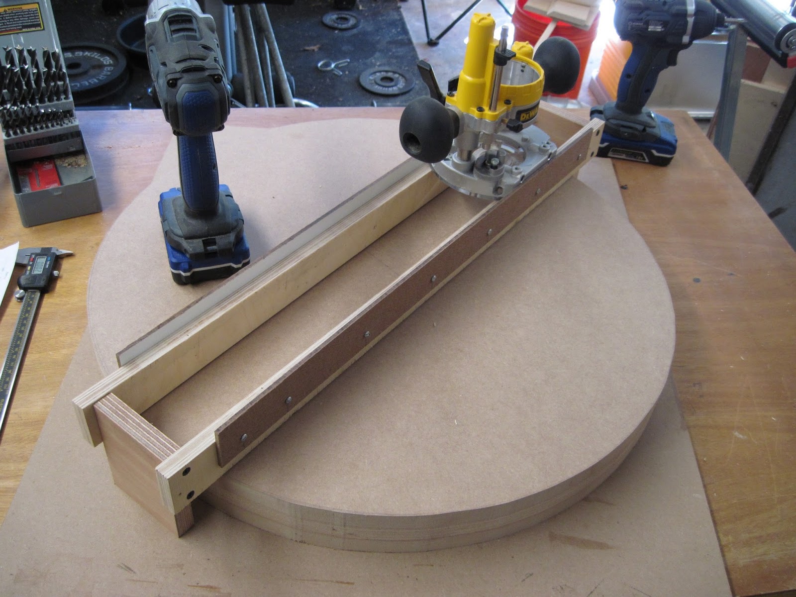
Below is a completed radius dish for sanding a radius curve in the sides of acoustic guitar bodies. Sandpaper will be adhered to the faces and the guitar sides will be placed on top and sanded until the very gentle radius curvature is placed on the edges. The guitar tops and backs have a slight radius curve to them, and this is what is used to do that.
Different radii are used for the backs and tops, and I chose 15' for the back and 35' for the top.
I used autocad to plot out the curvature and used a pair of calipers to mark the curve accurately onto two pieces of 13 layer, ~3/4" plywood. I cut it close with a bandsaw and finished with a block plane with the blade set just deep enough to 'flatten' out any imperfections. I set blocks up on each end (as shown) and added two guides of thin white faced board. The router shown slid back and forth, cutting the curvature into the disk made of MDF/3/4" ply/MDF. Above you can see the setup. The disk has a bolt up the center to allow it to spin as I cut. This was a very messy operation.
You can see here the curvature against the straightedge. I believe this is the 35' radius side. The other side has the 15'
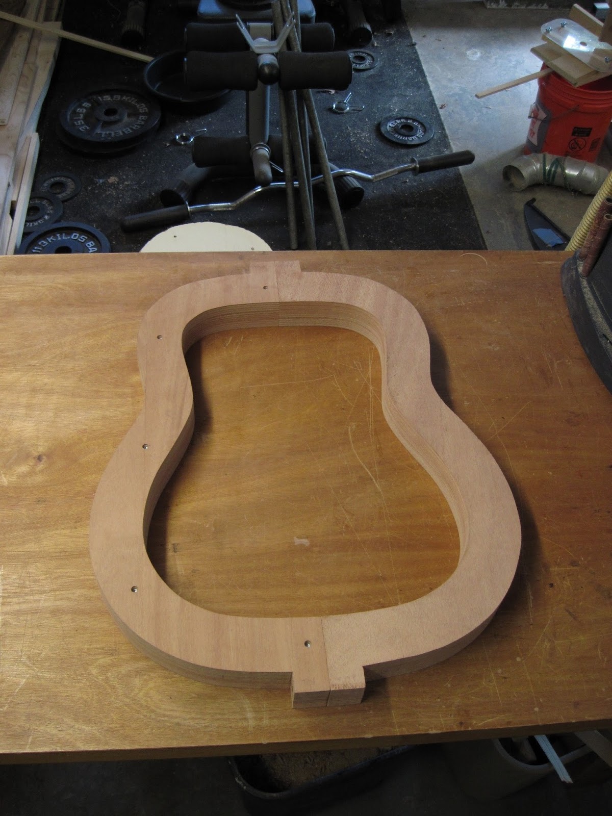
I needed a mold for sides of the guitar, so I cut the shape into a piece of 1/4" ply and used that to mark a 2-1/4" thick block of layered plywood. This template is based off of my Alvarez Model 5036 that I love so very much.
The plywood cut and bolted together. The scrap pieces inside were eventually worked to act as inside clamps for applying inward pressure using a turnbuckle, like this (
Side clamping jig).
This is a popular jig (O'Brien Neck Joint Jig) I reverse engineering. It is designed to cut neck tenons (foreground) and mortises (background). The tenon side can adjust to incorporate the proper neck angle. The 1/4" MDF templates are sized to form a snug fit.
This is the mortise side, where the guitar body is clamped. Cork helps to distribute the clamping pressure.
This is another reverse engineered jig for heat bending the guitar sides. The shape of the mold is a version of the above Alvarez template, but with slightly exaggerated curves to compensate for wood springback. The wood is placed in the jig with a heat blanket and spring steel to press the sides into shape.
Below is a handful of pictures documenting a thickness sander that will be used to thickness roughsawn guitar tops down to ~1/8". A thickness planer will not work for this application. I reverse engineered a number of design points for this project, but most of this is of my own design.
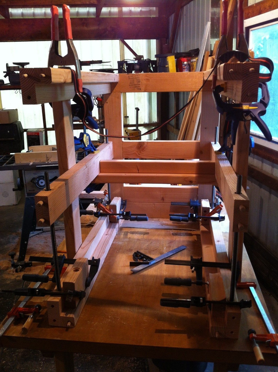
I begin with the frame. I hand picked 2x4 studs with as close to quartersawn grain as possible. I used a fence on the bandsaw to cut the mortises and tenons for a bridle joint. Each piece was planed for consistent thickness and width.
With a proper fence, the bandsaw cut cleanly without much need for touching up.
One side ready for gluing. A few dowels are used for some inside pieces.
Glued and clamped. Check for square.
The cross-member pieces are L shaped from one and a half pieces of 2x4. Dowels in the end connect to the sides.
Middle and top cross-members hold the bushings for height adjustment. These are silicon-bronze alloy bushings from McMaster Carr, counter bored into the cross-members. The center diameter of each is 1/2", chosen for the 1/2" acme lead-screws.
The final glue-up of the frame was complicated, since everything had to be square.
The middle cross-members had little braces between them, which made it even more difficult. The finished frame is visible in pictures below.
The bearing mounts for the main sanding drum shaft and guide drums are fabricated out of 3/4" ply and maple. The center bearing is for a 1" shaft, and the outer two mounts are for a spring loaded 1/2" feed roller shaft for applying pressure down towards the work piece.
A bunch of little pieces are required.
Competed mounts next to my AutoCAD drawings.
Springs will be placed on the two outer bolts to apply the pressure. A 5.25" V-belt pulley will couple with the 1" shaft.
Like this.
The standoffs mounted behind the plywood will be anchored into the frame
The main table for feeding the work piece will have bearings set into them for the conveyor belt. These two pieces will have slots cut into them for allowing the tensioning of the belt.
The set frame bushings from earlier were too out of alignment, so I designed these bushing mounts that will have more freedom for movement.
They are set into the frame, so some material was removed by first sawing a dado into the cross-member.
Rough fit test. Looks good.
The bulk of the conveyor belt table is constructed below.
A massive 25" wide table of 3 layers of 3/4" scrap birch plywood was glued together and eventually trimmed.
Slots were routed into the frame for the bearing mount assembly.
These 4 bits house 1/2" acme lead-screw nuts and are eventually mounted onto the conveyor belt table. Wood here is maple.
Using scrap MDF and 3/4" plywood, I cut out disks and marked the centers. These are for the conveyor belt rollers and feed rollers. They will be glued onto the 1/2" shafts.
This project is on hold for a few months until I finish remodeling the shop.
Jumping back in time, here is a liquor cabinet I designed and built with a coworker. Construction is all 1-by pine, with 2"x2" columns. I used biscuits to join the 'tiling' for the sides and mortise and tenons for the final assembly.
All 1-by pine was acclimated for a few weeks and then planed to a consistent thickness. The horizontal pieces attach to the 2x2 using M/T, and the wider tiles in the center are biscuited on all sides.
One side complete.
Similar for all the other sides.
Looks pretty nice considering it is all from Home Depot (I should find a better source at some point).
Some cross bracing under the drawer opening is a nice touch. All mortise and tenon there.
The door frames are mitered and glued. For extra rigidity, 2 splines were cut on each corner using my most infrequently used jig. I brought the saw outside this time since it was a lovely day.
Doors installed and corner gussets are in place. You can see the mortises on this side. The mount for the magnetic door catch is visible in the middle.
All together now. Drawer is made from some thinner pine, with an MDF bottom covered in cork. Full extension drawer glides worked great.
Out in the sun. The top is two 2x10s biscuit jointed together. I eventually cut a bevel on the bottom edges.
You can also see I tapered the 2x2 feet. I eventually added some shelves inside, stained the entire thing, and sealed it with semi-gloss polycrylic.
I checked out the finished product about a year later and it looks like it's in great shape. The drawer still functions perfectly, and the doors don't stick. I was worried since it's pine and can twist with temp/humidity changes.
I will post more soon. Expect updates on the remodeling project as well.
-Andrew