
I clamped the saw down to the table, along with the 1/3 HP motor on the side.

At this point I was able to spin the saw up for the first time. The wheel pitch, wheel height, wheel shaft position, and blade guide positions had to be adjusted. The tension of the blade held the bearings in place for testing.

Blade guide detail

Using the patented bearing-screwdriver technique, I balanced the wheels. I let the wheel settle with the heavy side down. I then taped a few pennies a fixed distance from the center. Once balanced, I calculated the equivalent volume of plywood to remove from the opposite side from the pennies. I drilled that volume out and the wheel was balanced. This method worked perfect the first time.

I determined the final wheel position and cut out some wooden washers and some thin cardboard to achieve the proper spacing. The same was done for the bottom.

A temporary MDF table was clamped to the trunnion beam.

I haven't used a bandsaw in years, so this was quite enjoyable. These are the trunnion cradles.

It is important for proper table function that the trunnions are shaped
perfectly. I determined the following method for achieving perfect
trunnions. This is tigerwood.

I first cut these rough shaped 'semi'-circles. The center points for the circles are included in the cuts.

A nail allows me to spin the pieces around and true the semi-circle edge.
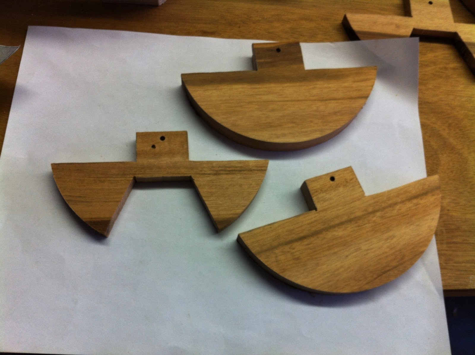
With all 6 pieces trued, I cut a notch for the center of the trunnions.

The nail helped me align the pieces for gluing and clamping.

Chopped off the center point 'nib' with the bandsaw.

Then cut out the inner curve and sanded it smooth.

After a few hours, I trued my trunnions. This involved pencil graphite to mark high points on the maple cradles. These high points were sanded down, and the process repeats until I was satisfied.

The sub-table was cut from 3/4" birch plywood. Nothing special. The trunnions were screwed onto the sides.

I align the center of the trunnions with the blade. I marked the bottom of the sub-table. This will help with placing the trunnion cradles onto the trunnion support beam.

The 'shop'.

After careful measuring and marking, I drilled the holes for the dowels on the trunnions support beam and cradles.

The dowels swell and essentially clamp the cradles in place. This is my first experience with dowel joints.

The trunnions fit perfectly on both sides. I couldn't have done it better. Everything's aligned and the trunnion center line is right where it should be. This picture also shows the lower wheel's stop on the shaft, consisting of a bolt and washer. The same was done on the upper wheel.

I marked on the trunnion cradles where the clamping bolt will go. This is determined by tilting the sub-table 45 degrees, and marking where the trunnions' inner slot stops. This basically means that the table will stop when it hits the bolt at 45 degrees.

The hole is drilled. The 1/4" carriage bolt sits in a small piece of maple inside the trunnion curve. The system works perfectly.
I have cut out the main table (in a very dangerous fashion) out of 2'x4' birch plywood. I have stained it a dark color, and will apply an epoxy finish using the same epoxy I used for my guitar. A maple trim will also be glued to the outside of the table.
All left is the main table, the motor, and the outer casing.

No comments:
Post a Comment